ВУЗ:
Составители:
Рубрика:

75
Fig. 13 Friction-stir
welding machine
The thermomechanically-affected zone lies between the HAZ and
nugget; the grains of the original microstructure are retained in this region,
but in a deformed state. The top surface of the weld has a different
microstructure, a consequence of the shearing induced by the rotating tool-
shoulder.
The Machine
This is a picture of a friction stir welding (FSW
shows a typical) machine. This one is at the Joining
and Welding Research Institute (JWRI) of Osaka
University, Japan.
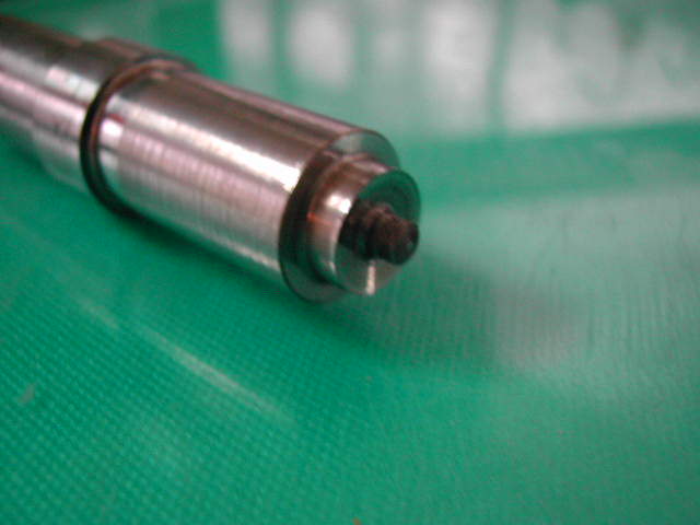
The Tool
Below you can see an illustration of some
types of tools. Each tool has a shoulder whose
rotation against the substrate generates most of the
heat required for welding. The pin on the tool is
plunged into the substrate and helps stir the metal in
the solid state.
Fig. 14 The tools
The Fixture and Weld
The two halves to be joined must be rigidly fixed before the welding
operation (first picture below). The pin, which is an integral part of the tool,
is plunged into the metal to help stir it up; the shoulder of the tool generates
much of the heat. As the weld is completed, the tool is withdrawn leaving
behind a hole. The weld is designed so that such regions can be discarded
from the component. The presence of a hole may not be appropriate when
welding pipes or storage vessels. The hole can be avoided by designing the
tool such that only the pin can be retracted automatically and gently into the
shoulder, leaving behind an integral weld.

Страницы
- « первая
- ‹ предыдущая
- …
- 73
- 74
- 75
- 76
- 77
- …
- следующая ›
- последняя »
